British Explosive Ordnance
Cluster Projectile 500lb No.14 Mk I (Service)

Fuzing: Nose Fuze No.42 Mk IV
Tail No.: No.42 Mk I

Contents: One hundred and six 4lb incendiary bombs
Overall length: 67 inches
Body diameter: 14 inches
Tail length: 21 inches
Tail diameter: 14 inches
Total weight: 450 pounds
Overall length: 67 inches
Body diameter: 14 inches
Tail length: 21 inches
Tail diameter: 14 inches
Total weight: 450 pounds
Fuzing: Nose Fuze No.42 Mk IV
Tail No.: No.42 Mk I
Color and markings: Dull red overall, one of the tensioning straps painted bright red
Description: The cluster comprises two fagots of 53 bombs each. The bombs in the two fagots are arranged nose-to-tail, and with their safety plungers inwards so that hey are all depressed. The bombs are held in place by a front end plate and a rear end plate, a top beam and a bottom beam, four wooden slats, tensioning straps, and a retaining bar having lateral pins which engage tabs on the tensioning straps. A shear wire passes through a bridge and the retaining bar at a position near the rear end plate. A channel, secured to the rear end plate, supports a fuze adapter, the outer end of which is closed by a transit plug fitted with a leather washer. Inside the adapter is a piston through which a pin is arranged to engage the lower end of a pivoted lever. The fuze adapter and the piston are slotted to receive the lever. The upper end of the lever is forked and is connected to the retaining bar. The rear end plate has two dowels for locating the tail in position, and a nut welded to the center of the rear end plate to receive one end of a tail tie rod when the tail unit is fitted to the cluster. A nose cover is fitted to the front end plate to decrease the drag of the cluster.
Tail Construction: The Tail Unit No.42 Mk I is a shortened drum-type tail, having a tail cone to which a tail ring is secured by fins. At the base of the tail cone are two holes to fit over the dowels on the rear end plate of the cluster. The tail unit is fitted with a bearing for an arming spindle, so that, if it should ever be required to fuze the cluster with an air armed fuze, a suitable arming spindle with an arming vane could be readily fitted. Also, to provide against this contingency, a bracket to receive a safety wire is welded to the tail cone and a hole passes through a projection on the support for the arming-spindle bearings. A tie rod passes through the center of the tail, and one end of the rod is screw threaded to go into the central nut of the rear end plate. Two windows, one of which is open, are provided in the tail cone. The open window is provided so that when the cluster is prepared for use, the fuzing link, connected to the pull percussion mechanism of the Fuze No.42 Mk IV, can be passed through it and connected to the fuzing unit of the bomb carrier.
Functioning: When a cluster is released from an aircraft, the fuze functions, and after a period of delay during which the cluster projectile falls freely, the fuze magazine charge is fired. The products of combustion of the magazine charge force the piston in the fuze adapter against the lower end of the pivoted lever, which is thus rocked about its pivot and exerts a pull on the retaining bar to break its shear wire, and to move so that the pins on the bar disengage the tabs on the tensioning straps. The straps then fly outwards and the cluster disintegrates, the component parts failing away separately. The individual 4lb bombs function on impact.
Suspension: A British type suspension lug is fitted to the top beam, and tapped holes in the beam are provided for fitting American type lugs.
Cluster Projectile 750lb No.15 Mk I (Service)


Contents: One hundred and fifty eight 4lb incendiary bombs
Overall length: 67 inches
Body diameter: 17.3 inches
Tail length: 21 inches
Tail diameter: 17.8 inches
Total weight: 668 pounds
Overall length: 67 inches
Body diameter: 17.3 inches
Tail length: 21 inches
Tail diameter: 17.8 inches
Total weight: 668 pounds
Fuzing: Nose Fuze No. 42 Mk IV
Tail No.: No.42 Mk I
Color and markings: Dull red overall, one tensioning strap painted bright red
Description: This cluster comprises two fagots of 79 bombs each. The bombs in each fagot are arranged nose-to-tail with their safety plungers inwards so that they are all depressed. The bombs are held in place by a front end plate and a rear end plate, a top beam and a bottom beam, four wooden slats, tensioning straps, and a retaining bar having lateral pins which engage tabs in the tensioning straps. A shear wire passes through a bridge and the retaining bar at a position near the end plate. A channel secured to the rear end plate supports a fuze adapter, the outer end of which is closed by a transit plug fitted with a leather washer. Inside the adapter is a piston through which is a pin arranged to engage the lower end of a pivoted lever. The fuze adapter and the piston are slotted to receive the level. The upper end of the lever is forked and is connected to the retaining bar. The rear end plate has two dowels for locating the tail in position, and a nut welded to the center of the rear end plate to receive one end of a tail tie rod when the tail unit is fitted to the cluster. A nose cover is fitted to the front end plate to decrease the drag of the cluster.
Tail Construction: The Tail Unit No.42 Mk I is a shortened drum-type tail, having a tail cone to which a tail strut is secured by fins. At the base of the tail cone are two holes designed to fit over the dowels on the rear end plate of the cluster. The tail unit is fitted with a bearing for an arming spindle so that, if it should ever be required to fuze the cluster with an air armed fuze, a suitable arming spindle with an arming vane could be readily fitted. Two windows, one of which is open, are provided in the tail cone. The open window is provided so that, when the cluster is prepared for use, the fuzing link connected to the pull-percussion mechanism of the Fuze No.42 Mk IV can be passes through it and be connected to the fuzing unit of the bomb carrier.
Functioning: When a fuzed cluster projectile is released, the fuze functions, and, after a delay during which the cluster projectile falls freely, the fuze magazine charge is fired. The products of combustion of the magazine charge force the piston in the fuze adapter against the lower end of the pivoted lever, which is thus rocked about its pivot and exerts a pull on the retaining bar of the cluster. This causes the retaining bar to break its shear wire and to be moved so that the pins on the bar disengage the taps on the tensioning straps. The straps then fly outwards and the cluster disintegrates, the component parts falling away separately. The individual 4lb bombs function on impact.
Suspension: A British type suspension lug is fitted to the top beam, and tapped holes in the beam are provided for fitting American type lugs.
Cluster Projectiles 1,000lb No.16 Mk II (Service)


Fuzing: Nose Fuze No. 42 Mk IV
Tail No.: No.48 Mks II and III


Contents: Two hundred and thirty five 4lb incendiary bombs
Overall length: 73.5 inches (approx.)
Body diameter: 18 inches (approx.)
Total weight: 935 pounds
Overall length: 73.5 inches (approx.)
Body diameter: 18 inches (approx.)
Total weight: 935 pounds
Fuzing: Nose Fuze No. 42 Mk IV
Tail No.: No.48 Mks II and III
Color and markings: Dull red overall, one tensioning strap painted bright red
Description: This cluster consists of three fagots of 4lb incendiary bombs. The bombs in each fagot are arranged nose-to-tail with their safety plungers inwards so that they are all depressed. The bombs are held in place by a front end plate, a rear end plate, a top and bottom beam, four wooden slats, tensioning straps, and a retaining bar. The retaining bar has a series of lateral pins which engage tabs on the tensioning straps. A shear wire passes through a bridge and the retaining bar at a position near the front end plate. A channel secured to the rear end plate supports a fuze adapter, the outer end of which is closed by a transit plug fitted with a leather washer. Inside the adapter is a piston, through which a pin is passed, arranged to engage the lower end of a pivoted lever. The fuze adapter and the piston are slotted to receive the level. The upper end of the lever is forked and is connected to the retaining bar. A nose cover is fitted to the front end plate to decrease the drag of the cluster. The tail unit is attached to a spring-loaded rod extending through the center of the cluster. the tail is held compressed against the spring by an arming wire arrangement.
Tail Construction: The Tail No.48 Mk II and III is of the telescopic type and is supplied fitted to the cluster in the closed position. It consists of five fairings, forming a shortened cone, carried by the rear end plate of the cluster, and a strut mounted on supports, carried by an inner tube which slides in an intermediate tube. The intermediate tube extends through the whole length of the outer tube, which is secured to the end plate of the cluster. The intermediate tube replaces the central bomb of the middle and tail-end fagot of the cluster.
A spring is housed in the inner tube, with one end bearing against a stop in the tube and the other end bearing against a cap which closes the inner end of the intermediate tube. The spring, which is under compression, tends to slide the inner tube out of the intermediate tube to extend the tail. This movement is limited by a ferrule on the inner tube, which engages a ferrule in the intermediate tube when the tail is fully extended.
The inner and intermediate tubes have holes provided in them, which register when the tail is closed. A safety wire is threaded through the holes to retain the tail in its closed position against the action of the spring. A 4-ft fuzing lanyard is attached to the eye of the safety wire by a shackle, and a similar shackle is provided at the free end of the lanyard.
Functioning: When a fuzed cluster projectile is released from the plane, the arming wire is withdrawn, starting the delay of the fuze and releasing the tail unit, which then springs out on its rod to the fully extended position. When the fuze functions, the fuze magazine charge is fired and the pressure of the gases forces the piston in the fuze adapter against the lower end of the pivoted lever. The lever is thus rocked about on its pivot and exerts a pull on the retaining bar of the cluster. This causes the retaining bar to break its shear wire and to be moved so that the pins on the bar disengage themselves from the tabs of the tensioning straps. The straps then fly outward, and the cluster disintegrates, scattering the bombs, which fall away separately. The individual incendiary bombs function on impact.
Suspension: A British type suspension lug is fitted to the top beam, and tapped holes in the beam are provided for fitting American type lugs.
Remarks: The fagot at the nose end of the cluster contains 79 bombs. The central and tail fagot contains 78 bombs each, the central bomb of each of these fagots being removed to allow insertion of the outer tube, which accommodates the stem of the tail and is secured to the rear end plate of the cluster.
Cluster Projectile 500lb No.17 Mk II (Service)

Fuzing: Tail Fuze No.885 Mk I
Tail No.: No.63 Mks I and II

Contents: Twenty six 20lb fragmentation bombs, specially designed for use in this cluster
Overall length: 63 inches (with blunt nose)
Width across flats: 15 inches (octagonal in shape)
Tail length: 27 inches
Total diameter: 17.5 inches
Total weight: 582 pounds
Overall length: 63 inches (with blunt nose)
Width across flats: 15 inches (octagonal in shape)
Tail length: 27 inches
Total diameter: 17.5 inches
Total weight: 582 pounds
Fuzing: Tail Fuze No.885 Mk I
Tail No.: No.63 Mks I and II
Color and markings: Dark green overall
Description: The cluster comprises twenty-six 20lb fragmentation bombs arranged in two fagots of thirteen bombs each. The bombs are held in place by a front end palte and a rear end plate, a top beam and a bottom beam, side plates, which overlap each other, and tensioning straps and a retaining bar, which hold the components together. The bombs are completely enclosed. Lateral pins on the retaining bar engage tabs forming part of shoes attached to the ends of the tensioning straps. A shear wire passes through the retaining bar and a bridge on the top beam. A channel secured to the rear end plate supports a fuze adapter, the outer end of which is closed by a transit plug and leather washer. Inside the adapter is a piston through which is a pin to engage the lower end of a pivoted lever. The fuze adapter and piston are slotted to receive the lower end of the lever. The lever passes into the fuze adapter. Links connect the upper end of the lever to a downwardly projecting plate, welded to the retaining bar. The rear end plate has two dowels for locating the tail in position, and a nut welded to the center of the plate to receive one end of a tail tie rod, when the tail unit is fitted to the cluster. The front end plate has two dowels for locating either a blunt nose fairing or a streamlined nose fairing in position, and a nut welded to the center of the plate to receive the securing stud of the blunt nose fairing, or the tie rod of the streamlined fairing. The blunt nose fairing is fitted to the cluster if it is to be carried internally in an aircraft. The streamlined nose fairing consists of a hollow metal dome, the base of which is partly covered by an end plate welded to the dome, and is to be fitted to the cluster when carried externally on an aircraft.
Tail Construction: The Tail Unit No.63 Mk I consists of a tail cone, having an approximately octagonal base and a tail strut secured to the cone by six supports. The tail unit has an arming spindle mounted in bearings, and has a fork at its inner end and an arming vane at its outer end. Two inspection windows in the tail cone are provided to enable the armorer to watch the fork of the arming spindle, when fitting the tail unit to a cluster fuzed with a Tail Fuze No.855. The Tail No.63 Mk I is only used when the cluster is carried internally in an aircraft. The Tail No.63 Mk II is similar to the Mk I, except that it is generally strengthened and has seven tail drum supports as compared with the six of the Tail No.63 Mk I, and is to be used when the cluster is carried externally on the aircraft.
Functioning: When the fuzed cluster projectile is released, the fuze functions, and, after a period of delay during which the cluster falls freely, the fuze magazine is fired. The products of combustion of the magazine charge force the piston in the fuze adapter against the lower end of the pivoted lever, which is thus rocked about its pivot and exerts a pull on the retaining bar of the cluster. The pull breaks the shear wire passing through the retaining bar and moves the bar so that its pins disengage the tabs on the tensioning straps. The straps then fly outwards and the cluster disintegrates. Its component parts fall away separately and the individual bombs descend, supported by their parachute, to function in the normal manner.
Suspension: A British type suspension lug is fitted to the top beam, and tapped holes in the top beam are provided for fitting American type lugs.
Cluster Projectile 350lb No.23 Mk I, and 500lb No.24 Mk I (Service)

350lb No.23 Mk I
Fuzing: Tail Fuze No.885 Mk I
Tail No.: No.65 Mk I
500lb No.24 Mk I
Fuzing: Tail Fuze No.885 Mk I
Tail No.: No.66 Mk I

350lb No.23 Mk I
Contents: Fourteen modified US 20lb fragmentation bombs
Overall length: 62.25 inches
Body diameter: 11.1 inches
Tail length: 27.5 inches
Tail diameter: 12.6 inches
Total weight: 335 pounds
Overall length: 62.25 inches
Body diameter: 11.1 inches
Tail length: 27.5 inches
Tail diameter: 12.6 inches
Total weight: 335 pounds
Fuzing: Tail Fuze No.885 Mk I
Tail No.: No.65 Mk I
500lb No.24 Mk I
Contents: Twenty modified US 20lb fragmentation bombs
Overall length (blunt nose): 62.25 inches
Overall length (streamlined nose): 71.75 inches
Body diameter: 14.5 inches
Tail length: 30.5 inches
Tail diameter: 18 inches
Total weight: 467 pounds
Overall length (blunt nose): 62.25 inches
Overall length (streamlined nose): 71.75 inches
Body diameter: 14.5 inches
Tail length: 30.5 inches
Tail diameter: 18 inches
Total weight: 467 pounds
Fuzing: Tail Fuze No.885 Mk I
Tail No.: No.66 Mk I
Color and markings: Dark green overall, one tensioning strap painted red.
Description: These clusters are identical in construction, and function in a similar manner. The Cluster No.23 Mk I, however, is approximately hexagonal in cross-section, while the No.24 Mk I is roughly octagonal.
The bombs forming the cluster are retained in two fagots of 7 bombs each in the No.23 and 10 bombs each in the No.24 by means of top and bottom beams, front and rear end plates, side fairing, and four tensioning straps. The tensioning straps are held in position by lateral pegs on the release rod, which is carried on the top beam. The release rod is connected to a lever and piston mechanism, the cylinder of which also forms an adapter for the barometric fuze and is located on the rear end plate. Before the fuze is fitted, the adapter is closed by a washered plug.
The cluster is converted into an amiable cluster by the addition of a blunt nose fairing and a drum-type tail. A special streamlined nose fairing is designed only for the Cluster No.24 Mk I, when it is to be stowed externally on the aircraft.

Tail Construction: The Tail Unit No.66 Mk I of the Cluster No.24 consists of a tail cone having an approximately octagonal base to which a circular strut is attached by seven tail fins. The cone is fitted with the conventional arming assembly consisting of arming vanes, arming spindle, and an arming fork. The tail is fastened to the cluster by a tie rod, and has two dowel holes in its base to position it. The cone is fitted with two inspection windows.
The Tail Unit No.65 Mk I is similar to the No.66 Mk I except that it has a hexagonal base, and only six tail pins.
Functioning: On release from the aircraft, the cluster falls until the fuze functions. The explosion in the magazine forces the piston forward in its housing and causes a rocking movement of the pivoted lever. The sudden movement of the lever exerts a pull on the retaining bar and breaks the shear wire, disengaging the lateral pins from the tabs of the tensioning straps. The straps are thus released and fly outwards, releasing the bombs.
Suspension: A British type suspension lug is fitted to the top beam, and two crutching pads bolted to the beam are used when a British type bomb carrier is fitted to the cluster. Two sets of four tapped holes are provided in the top beam for the attachment of American type suspension lugs. Two of the four holes at the nose end of the beam normally house the bolts securing one of the crutching pads to the beam. If American type lugs are fitted, the British type lug and crutching pads must first be removed.
Nose Ejection Clusters


General Information: Experts have long strived to obtain a better type of cluster projectile, because of the inherent problems of aiming accuracy, dispersion of contents, weight factor, etc., presented by this type of ordnance. The British believe that the solution to the search lies in the use of the Nose Ejection type cluster described herein, or its successor as modified by further research.
Nose ejection clusters were put into production near the end of World War II. The information presented here is a generalized summary of nose ejection clusters, due to the fact that many of the individual clusters of this type are still in the developmental stage.
Nose ejection clusters were put into production near the end of World War II. The information presented here is a generalized summary of nose ejection clusters, due to the fact that many of the individual clusters of this type are still in the developmental stage.
General Requirements: The fundamental requirement of any cluster is to provide a means of placing cluster contents effectively on the target, the effectiveness being regarded broadly as a function of the angle and velocity of strike, functioning of fuzes or strikers, density of pattern, and accuracy of aim. Complementary requirements of equal importance are that the cluster shall provide an economical aircraft bomb load, that its preparation for use shall be simple and speedy, that it will withstand road, rail, and ship transport without endangering its safety or usefulness, and that it will meet the strength requirements specified for carriage of bombs in British and American aircraft.
The type of nose ejection cluster now being developed and in production goes far towards meeting these requirements in a simple and direct manner. It is not possible to generalize on the stability of nose ejection clusters as a group, since this depends on weight and dimensional characteristics, which are mainly due to the type of cluster contents carried. Ballistic stability resulting in an aiming error of between 2 and 6 mils is being obtained, and will be improved upon as the development of folding and telescopic tails progresses.
The effectiveness of cluster contents from nose ejection clusters is largely fortuitous. It appears to depend mainly on the inherent stability of the cluster contents and the parent cluster, although the velocity and height of disintegration of the cluster has some bearing. Control of cluster velocity at disintegration is a problem now being explored. Earlier investigation showed that decreased velocity at disintegration is invariably accompanied by a closing in of the scatter pattern, and much work on the control of the scatter pattern remains to be done.
Increasing the size of scatter patterns by means of attachments to the cluster contents and asymmetric parasheets is being investigated, but the results so far obtained, though promising, do not justify immediate embodiment.
Body Construction: The cluster body consists of a cylindrical steel shell made from 10- or 12-gauge steel plate, and is closed at the rear end by a steel plate of similar gauge, which is welded in position. Two fuze pockets, which are deep enough to accommodate the burster ejectors, are attached to the end plate, which also embodies a centrally tapped hole for attaching the cluster tail. A test plug, by which air pressure is applied at the filling factory to check that the rubber sealing joints in the nose are properly tight, is also provided in this plate. The end plate is shaped to form a shallow truncated cone, the sloping surface of which locates the tail centrally on the cluster body. The nose end of the cluster is closed by an iron casting secured in place by a number of screws. On the inside of the casting is an internal steel squash plate secured by a central screw. Its purpose is to compress the rubber sealing ring against the internal surface of the cluster body to exclude air. A knife is attached at the front end of the cluster for the purpose of cutting the steel straps as the fagot of cluster contents is ejected. A pressure plate is assembled in the cluster behind the fagot of cluster contents. Suspension lugs for British and American type bomb stowage are permanently attached to the cluster body.
The cluster is designed, manufactured, and tested to withstand the climatic conditions experienced in the Far East. After assembly at the filling factory, the rubber sealing joints in the nose and under the knife fixing screws are tested for tightness by an air-pressure test.
Tail Construction: Two types of cluster tail are in use, the conventional type with a tail cone and cylindrical strut, and one having collapsible fins, which is used where the space available is too small to permit the use of a norm-type tail. Twin arming mechanisms are locked by means of fuzing wires engaging holes in the arming vanes. Windows are provided through which the fuze can be observed as the tail is assembled to the cluster. The tail is located on the tapered end plate of the cluster body, and is secured by a single central bolt. It is designed, manufactured, and boxed for use in tropical climates.
Transit Bases: To prevent the cluster from sustaining damage affecting the safety of its contents, or destroying the hermetic seal in the nose, each cluster is fitted with transit bases which are intended to remain in position until the cluster is prepared for use.
The transit bases consist of two light-gauge steel rings filled with a material designed to withstand shock loads resulting from rough handling, and also to distribute the load over a large area of the cluster and so prevent damage to the nose seal, which would inevitably result from a blow concentrated at any one point on the nose cover. The material used in the Mk I design is a resin-bonded sawdust, which is light in weight and resistant to tropical climatic conditions, fungi and insect growth, etc. The bases are fitted one at each end of the cluster, and secured by tie rods, which embody a quick release device designed to enable the bases to be removed in a minimum of time.
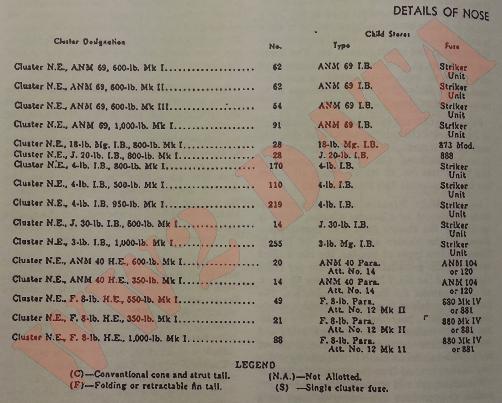
Fuzing: One fuze and burster only are necessary to disintegrate the cluster, but two of each are used as an insurance against complete failure. Clusters containing 4lb I.B.'s are fuzed with two Tail Fuzes No.42 Mk IV, while all others use two Barometric Tail Fuzes No.886.
Burster Ejectors: Ejection of the cluster contents in effected by a burster ejector, which is ignited by the cluster fuze. The bursters are placed in the cluster at the time of fuzing. There are two types of burster, the No.6 Mk I containing 70 grams of G.20 powder for large clusters and the No.7 Mk I containing 50 grams of G.20 powder for the smaller clusters. The powder is contained in a plastic cylinder manufactured from a polyvinal chloride. This material is fully resistant to tropical conditions and does not affect the gunpowder. The cylinders are provided with two small extrusions by which they can be removed from the cluster if required.
For transport and storage the bursters are packed two or four (according to suze) in a sealed metal cylinder, 18 of which are packed in one wooden box. The metal cylinders are opened by means of a tear-off metal strip.
Contents: The cluster contents are assembled in two or more banks of bombs, with light-gauge steel end plates and longitudinal steel struts, to form a fagot, which is firmly secured by a number of circumferential steel straps. When properly assembled to a fagot, the cluster contents are safe and the fuzes cannot arm accidentally. Damage to components of the cluster contents by the force of the ejector charge is prevented by the steel struts, which transmit the force of the explosion from the pressure plate directly to the nose cover, and not through the bombs themselves.
Functioning: On release from the aircraft, the fuzing lanyards are withdrawn from the fuzes and from the air arming vanes. When a folding tail is used, the lanyard is also withdrawn from the retaining device to allow the tail to assume an expanded position. At a predetermined height the fuzes operate and ignite the burster. The expanding gases from the burster drive the fagot of contents forward. As the fagot passes the cutting edge of the knife, the steel straps binding the cluster are severed, and the screws holding the cluster noose in place are broken. The contents are then fully ejected.
Developmental Priority: The following is a list of nose ejection clusters in order of their development priority. The first six items were cleared for production on 7 July, 1945.
Cluster N.E., ANM 69 I.B., 500lb. Mks I & II
Cluster N.E., 18-lb Mg. I.B., 800lb. Mk I
Cluster N.E., J 20-lb I.B., 800lb. Mk I
Cluster N.E., ANM 40 H.E., 600lb. Mk I
Cluster N.E., ANM 40 H.E., 350lb. Mk I
Cluster N.E., F. 8-lb H.E., 550lb. Mk I
Cluster N.E., F. 8-lb H.E., 350lb. Mk I
Cluster N.E., F. 8-lb H.E., 1,000lb. Mk I
Cluster N.E., ANM 69 I.B., 550lb. Mk III
Cluster N.E., 4-lb I.B., 800lb. Mk I
Cluster N.E., J. 30-lb I.B., 500lb. Mk I
Cluster N.E., 4-lb I.B., 500lb. Mk I
Cluster N.E., 4-lb I.B., 950lb. Mk I
Cluster N.E., ANM 69 I.B., 1,000lb. Mk I
Cluster N.E., 3-lb I.B., 1,000lb. Mk I


The type of nose ejection cluster now being developed and in production goes far towards meeting these requirements in a simple and direct manner. It is not possible to generalize on the stability of nose ejection clusters as a group, since this depends on weight and dimensional characteristics, which are mainly due to the type of cluster contents carried. Ballistic stability resulting in an aiming error of between 2 and 6 mils is being obtained, and will be improved upon as the development of folding and telescopic tails progresses.
The effectiveness of cluster contents from nose ejection clusters is largely fortuitous. It appears to depend mainly on the inherent stability of the cluster contents and the parent cluster, although the velocity and height of disintegration of the cluster has some bearing. Control of cluster velocity at disintegration is a problem now being explored. Earlier investigation showed that decreased velocity at disintegration is invariably accompanied by a closing in of the scatter pattern, and much work on the control of the scatter pattern remains to be done.
Increasing the size of scatter patterns by means of attachments to the cluster contents and asymmetric parasheets is being investigated, but the results so far obtained, though promising, do not justify immediate embodiment.
Body Construction: The cluster body consists of a cylindrical steel shell made from 10- or 12-gauge steel plate, and is closed at the rear end by a steel plate of similar gauge, which is welded in position. Two fuze pockets, which are deep enough to accommodate the burster ejectors, are attached to the end plate, which also embodies a centrally tapped hole for attaching the cluster tail. A test plug, by which air pressure is applied at the filling factory to check that the rubber sealing joints in the nose are properly tight, is also provided in this plate. The end plate is shaped to form a shallow truncated cone, the sloping surface of which locates the tail centrally on the cluster body. The nose end of the cluster is closed by an iron casting secured in place by a number of screws. On the inside of the casting is an internal steel squash plate secured by a central screw. Its purpose is to compress the rubber sealing ring against the internal surface of the cluster body to exclude air. A knife is attached at the front end of the cluster for the purpose of cutting the steel straps as the fagot of cluster contents is ejected. A pressure plate is assembled in the cluster behind the fagot of cluster contents. Suspension lugs for British and American type bomb stowage are permanently attached to the cluster body.
The cluster is designed, manufactured, and tested to withstand the climatic conditions experienced in the Far East. After assembly at the filling factory, the rubber sealing joints in the nose and under the knife fixing screws are tested for tightness by an air-pressure test.
Tail Construction: Two types of cluster tail are in use, the conventional type with a tail cone and cylindrical strut, and one having collapsible fins, which is used where the space available is too small to permit the use of a norm-type tail. Twin arming mechanisms are locked by means of fuzing wires engaging holes in the arming vanes. Windows are provided through which the fuze can be observed as the tail is assembled to the cluster. The tail is located on the tapered end plate of the cluster body, and is secured by a single central bolt. It is designed, manufactured, and boxed for use in tropical climates.
Transit Bases: To prevent the cluster from sustaining damage affecting the safety of its contents, or destroying the hermetic seal in the nose, each cluster is fitted with transit bases which are intended to remain in position until the cluster is prepared for use.
The transit bases consist of two light-gauge steel rings filled with a material designed to withstand shock loads resulting from rough handling, and also to distribute the load over a large area of the cluster and so prevent damage to the nose seal, which would inevitably result from a blow concentrated at any one point on the nose cover. The material used in the Mk I design is a resin-bonded sawdust, which is light in weight and resistant to tropical climatic conditions, fungi and insect growth, etc. The bases are fitted one at each end of the cluster, and secured by tie rods, which embody a quick release device designed to enable the bases to be removed in a minimum of time.
Fuzing: One fuze and burster only are necessary to disintegrate the cluster, but two of each are used as an insurance against complete failure. Clusters containing 4lb I.B.'s are fuzed with two Tail Fuzes No.42 Mk IV, while all others use two Barometric Tail Fuzes No.886.
Burster Ejectors: Ejection of the cluster contents in effected by a burster ejector, which is ignited by the cluster fuze. The bursters are placed in the cluster at the time of fuzing. There are two types of burster, the No.6 Mk I containing 70 grams of G.20 powder for large clusters and the No.7 Mk I containing 50 grams of G.20 powder for the smaller clusters. The powder is contained in a plastic cylinder manufactured from a polyvinal chloride. This material is fully resistant to tropical conditions and does not affect the gunpowder. The cylinders are provided with two small extrusions by which they can be removed from the cluster if required.
For transport and storage the bursters are packed two or four (according to suze) in a sealed metal cylinder, 18 of which are packed in one wooden box. The metal cylinders are opened by means of a tear-off metal strip.
Contents: The cluster contents are assembled in two or more banks of bombs, with light-gauge steel end plates and longitudinal steel struts, to form a fagot, which is firmly secured by a number of circumferential steel straps. When properly assembled to a fagot, the cluster contents are safe and the fuzes cannot arm accidentally. Damage to components of the cluster contents by the force of the ejector charge is prevented by the steel struts, which transmit the force of the explosion from the pressure plate directly to the nose cover, and not through the bombs themselves.
Functioning: On release from the aircraft, the fuzing lanyards are withdrawn from the fuzes and from the air arming vanes. When a folding tail is used, the lanyard is also withdrawn from the retaining device to allow the tail to assume an expanded position. At a predetermined height the fuzes operate and ignite the burster. The expanding gases from the burster drive the fagot of contents forward. As the fagot passes the cutting edge of the knife, the steel straps binding the cluster are severed, and the screws holding the cluster noose in place are broken. The contents are then fully ejected.
Developmental Priority: The following is a list of nose ejection clusters in order of their development priority. The first six items were cleared for production on 7 July, 1945.
Cluster N.E., ANM 69 I.B., 500lb. Mks I & II
Cluster N.E., 18-lb Mg. I.B., 800lb. Mk I
Cluster N.E., J 20-lb I.B., 800lb. Mk I
Cluster N.E., ANM 40 H.E., 600lb. Mk I
Cluster N.E., ANM 40 H.E., 350lb. Mk I
Cluster N.E., F. 8-lb H.E., 550lb. Mk I
Cluster N.E., F. 8-lb H.E., 350lb. Mk I
Cluster N.E., F. 8-lb H.E., 1,000lb. Mk I
Cluster N.E., ANM 69 I.B., 550lb. Mk III
Cluster N.E., 4-lb I.B., 800lb. Mk I
Cluster N.E., J. 30-lb I.B., 500lb. Mk I
Cluster N.E., 4-lb I.B., 500lb. Mk I
Cluster N.E., 4-lb I.B., 950lb. Mk I
Cluster N.E., ANM 69 I.B., 1,000lb. Mk I
Cluster N.E., 3-lb I.B., 1,000lb. Mk I

Next Time: High Explosive Rockets Part 1


